What do UML Class Diagrams mean?
 Sat 2004-08-28
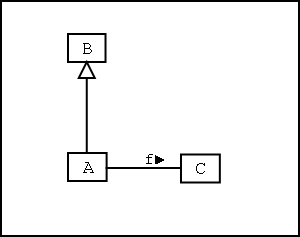
 Consider the following UML class diagram:
What does this diagram say? What does it mean? What does it actually constrain?
There is a lot of UML literature which purports to give a semantics to the UML. However, these forms of semantics are either expressed in words, and are therefore ambiguous and imprecise, or else are minutely detailed mathematical models of box and arrow diagrams intended for the implementors of UML diagramming tools. Both of these are inadequate if what you want to do is to reason about specifications.
I suggest that the semantics of the above diagram is best expressed using first-order predicate logic as follows:
∀a . a∈A ⇒ (a∈B ∧ f(a)∈C)
It would also be possible to express this in terms of the subset relationship and relational image:
A⊆B ∧ f(|A|)⊆C
However, I prefer to make the quantifier and its variable explicit (the latter is analogous to the implicit self variable in object oriented class definitions). I also prefer to use Lamport's prefix layout for conjuctions and disjunctions. This is the way I would normally write this specification:
∀a . a∈A ⇒
∧ a∈B
∧ f(a)∈C
Note that this does not require that any A's (or B's or C's) actually exist. It only requires that if they do then they must be constrained in the above way (ie: they must also be members of B, and when function f is applied to them it must return a member of C).
Note also that the above specification is extendible. The use of implication allows us to later add further constraints. This is consistent with the idea that UML diagrams are partial views of the complete system.
Also, the specification says nothing about the value returned by the function f when it is applied to a value that is not in A. In that case the returned value is unconstrained (for example, we cannot say whether it is in C or not in C).

Reader Comments